Guide Schematic Views
On the origami guide schematic, DNA helices are represented as straight lines for simplicity. Nodes can be dragged with the mouse and the layout re-equalises in a fluid way. Alternatively, forces can be turned off. The layout leverages the excellent Force Graph and 3D Force Graph engines.
The ‘Toggle View’ button at the top of the guide schematic can be used to put the schematic in three different display modes, explained below.
Scaffold View
The Scaffold View emphasises the route taken by the (long) scaffold strand through the origami nanostructure. Arrows point in direction of scaffold 5’ to scaffold 3’ (except the grey staple crossover arrows). On hovering the mouse over a domain, the blue sequence listed in the pop-up box is the scaffold sequence (listed 3’ to 5’).
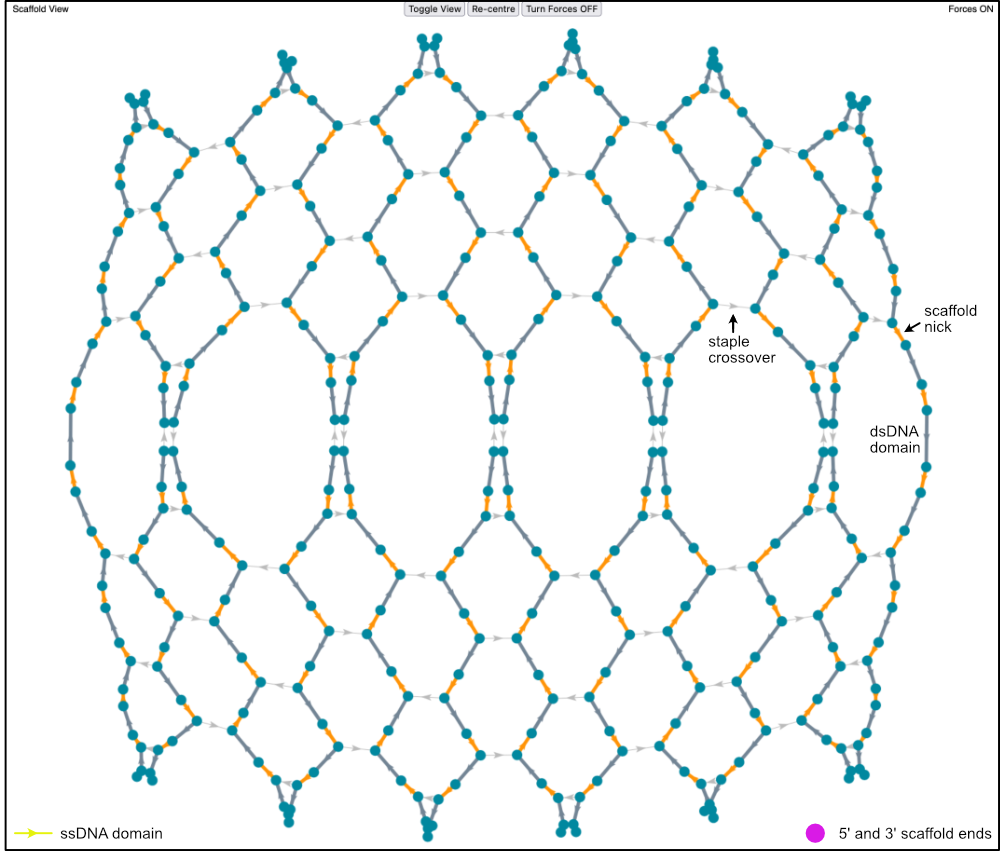
Linear scaffolds have 5’ and 3’ scaffold ends marked with purple nodes. The guide schematic below has a circular scaffold, and scaffold end nodes are not present.
Any sections of scaffold not hybridised to staples are marked as yellow domains. The guide schematic above has no ssDNA scaffold sections.
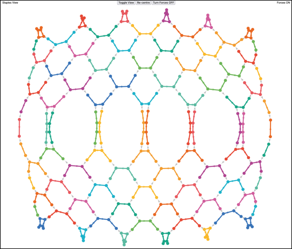
Staples View
The Staples View highlights all individual staples in different colours. Arrows on the coloured staples point in the staple 5’ to staple 3’ direction. Arrows showing scaffold nicks still show the 5’ to 3’ direction of the scaffold. On hovering the mouse over a staple section, the white sequence listed in the pop-up box is the staple sequence (listed 5’ to 3’).
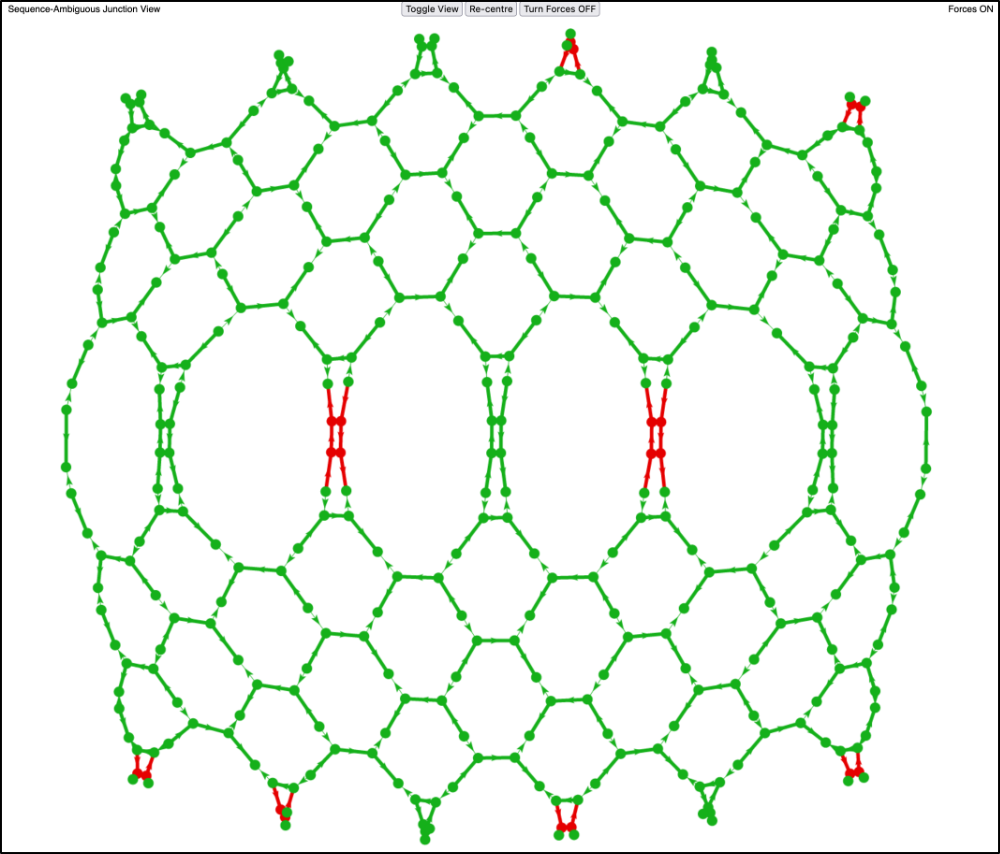
Sequence-Ambiguous Junction View
The Sequence-Ambiguous Junction View shows which parts of the origami are completely constrained by sequence complementarity. It helps identify areas where REVNANO could have made errors in reconstructing the contact map (and bound those errors).
Green junctions on the origami cannot be moved without breaking sequence complementarity at some point. Hence, with certainty, green junctions are correctly placed by the REVNANO solver.
Red junctions can be moved and still retain staple-scaffold sequence complementarity. Red junctions are ambiguous and may or may not be correctly placed by the REVNANO solver.
Note
Often, it is the case that Holliday junctions (back to back staple crossovers) admit a certain amount of ‘slide’ whilst retaining staple-scaffold sequence complementarity in all positions.
More specifically, a red node on the graph corresponds to the end of a hybridised domain between a staple and the scaffold, where the hybridised domain may be made shorter or longer (and the associated local hybridisation changes propagated) without breaking local sequence complementarity between scaffold and staples.
Hovering the mouse over a red node on the graph shows a message like {ambig -1 to +1}.
This means that, from its currently displayed position, the red node can be moved 1 base position ‘back’ in the direction of the scaffold 5’ (the -1 part), which may either shorten or lengthen the hybridised domain it is part of. Or, it can be moved 1 base position ‘forwards’ toward scaffold 3’ (the +1 part), which may either lengthen or shorten the hybridised domain it is part of. Hence, the domain can be three different lengths at the red node end, without scaffold-staple sequence complementarity being broken.
Often looking at the global origami design schematic, and by using symmetry, positions of the non-ambiguous green junctions can inform where the positions of the ambiguous red junctions are in the original origami design.
An origami with all green junctions (and all staples placed) unambiguously embeds its entire staples-scaffold contact map within its sequences.
The presence of some moveable junctions may also have implications for self-assembly accuracy.
Export High Resolution Image
Export a hi-resolution screen shot of your current guide schematic view in Firefox, by pressing alt-cmd-k to open the browser Console, and then type:
:screenshot --dpr 1 --fullpage
The resolution can be increased by increasing the number 1 (decimal numbers are allowed).